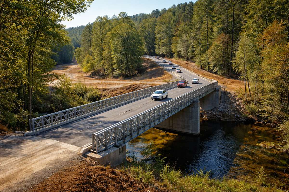


What It Actually Takes to Keep a Highway Bridge Standing: Inspection, Scanning, and Structural Repair
4.9 billion vehicle trips cross US bridges every single day. Most drivers don’t give it a second thought. They probably should.
According to the FHWA National Bridge Inventory from June 2025, the United States has 624,193 bridges with an average age of 47 years – right against the standard 50-year design life. Of those, 41,685 are currently rated in poor condition. That’s not a rounding error. It means 168 million daily vehicle trips are crossing structures the federal government classifies as structurally deficient.
The 2025 ASCE Infrastructure Report Card gave bridges a C grade. Nearly half the inventory – 49.6% – sits in “fair” condition, one category away from poor. That transition from fair to poor rarely looks dramatic from outside the structure. It happens from the inside out: rebar corrodes below intact-looking concrete, post-tension cables degrade inside box girders, internal voids open up along slab interfaces. Surface inspection catches the results, not the cause.
Modern infrastructure preservation works in two phases that policy discussions regularly undervalue. The first is subsurface scanning – locating hidden deterioration before it reaches the surface. The second is precision structural treatment that addresses what the scan finds. Both are essential. This article covers each phase and why treating them as separate, disconnected work orders is a mistake.
Why Visual Inspection Alone Isn’t Enough
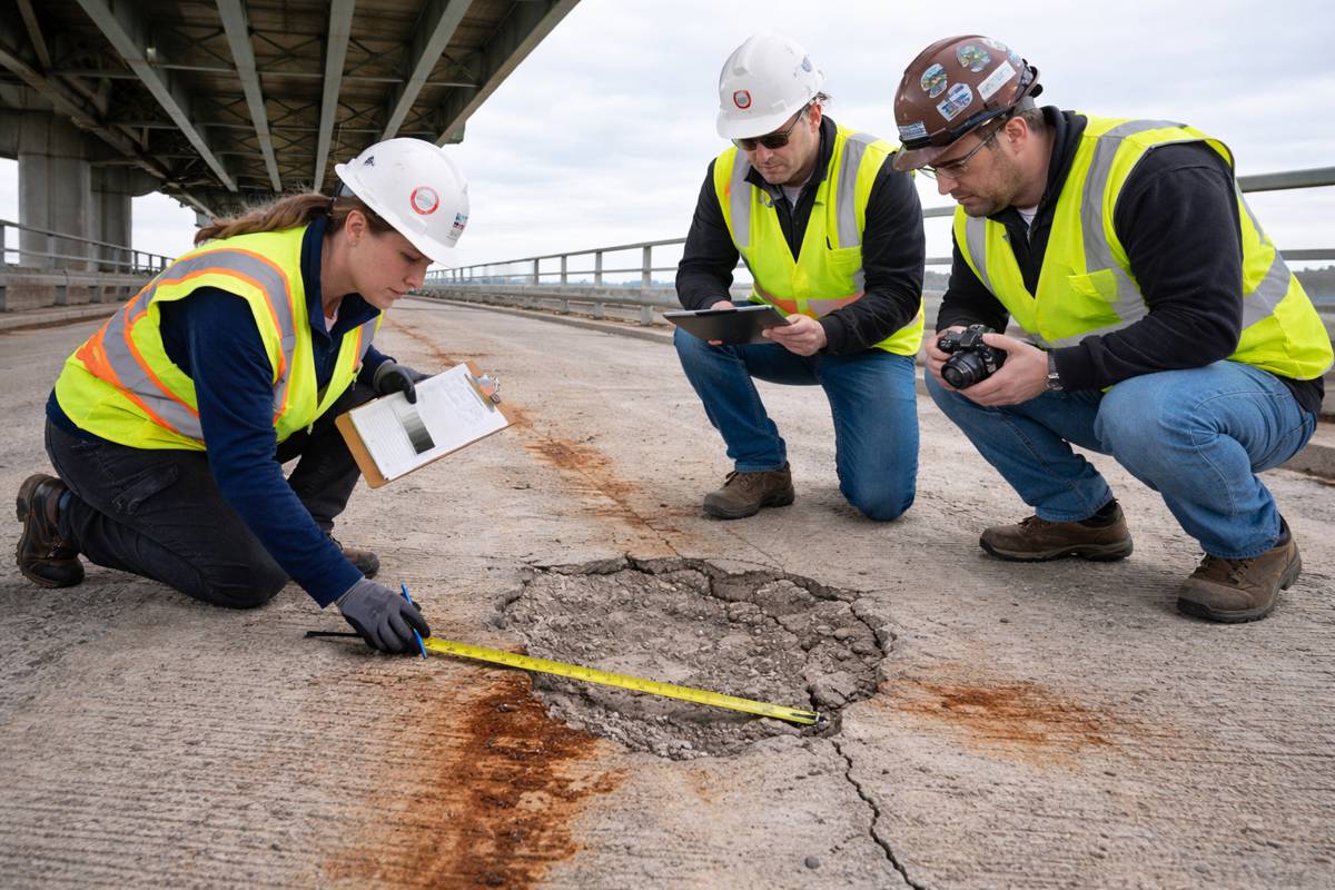
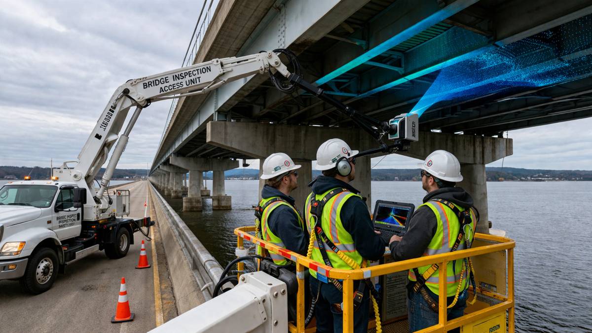
Traditional bridge inspection follows a structured cycle: scheduled visual assessments, hands-on probing, periodic concrete core samples, and photographic documentation. Federal standards require inspection every 24 months for most National Highway System bridges. That system has genuine value. It catches surface spalling, visible cracking, exposed rebar, joint failures, and drainage problems.
But it misses a lot. Rebar corrosion beneath intact-looking surface concrete can progress for years without visible symptoms. Post-tension cable degradation inside a box girder bridge is essentially invisible without intrusive testing. Internal delamination – where the bond between concrete layers has failed – often shows nothing at the surface until the slab starts to drop. By the time these failure modes are visible, repair scope has already expanded significantly.
The FHWA’s 23rd Edition Status of the Nation’s Highways, Bridges, and Transit reflects a growing federal recognition that scheduled visual inspection can’t keep pace with the rate of deterioration now present in the inventory. The federal framework now calls for systematic non-destructive evaluation across the National Highway System – a clear signal that the 24-month visual cycle needs to be supplemented, not just repeated.
The replacement-rate math from the 2025 ASCE Report Card sharpens the stakes: at current rates, new bridges must last 126 years to keep up with demand, yet they’re designed for 50. Meanwhile, data-driven tools now tracking highway conditions in real time are giving agencies better situational awareness than ever – but surface sensors and drone cameras still don’t tell you what’s happening inside the deck.
That’s where GPR concrete scanning comes in – specialist firms whose equipment maps rebar corrosion, internal voids, and delamination that surface inspection can’t detect.
GPR Concrete Scanning: Reading the Hidden Interior of Highway Infrastructure
Specialist firms deploying GPR concrete scanning technology have become a standard part of serious bridge maintenance programs – their equipment maps what no visual inspection can see.
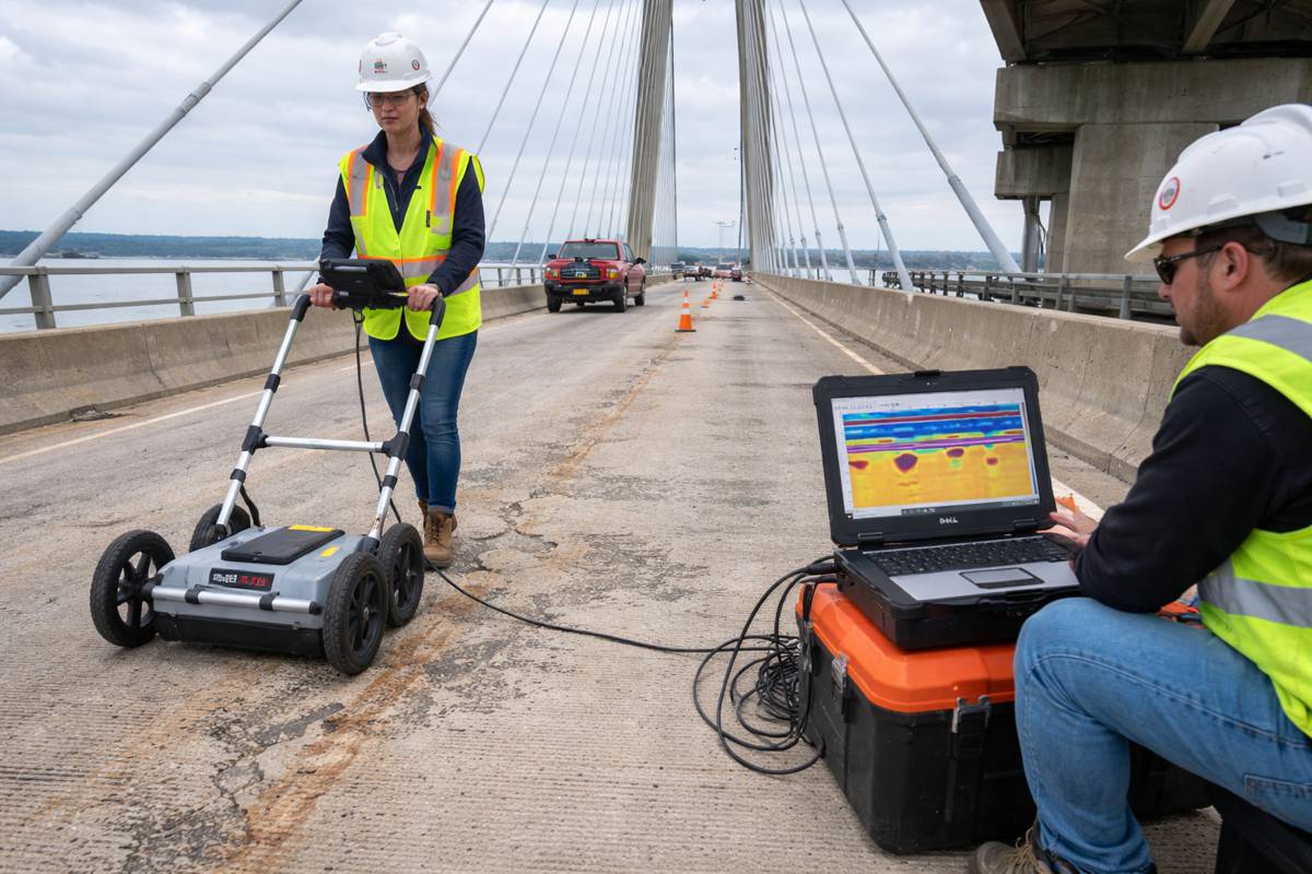
GPR works by emitting high-frequency radar pulses into concrete and measuring the two-way travel time as those pulses reflect off subsurface features. The system uses the dielectric properties of the concrete to build a continuous subsurface profile: rebar position and depth, post-tension cable locations, slab thickness, moisture intrusion zones, internal voids, and delamination. All of it without a single drill hole.
Corrosion detection works through signal quality. A strong reflection with high amplitude indicates sound rebar with good bond to surrounding concrete. A weak reflection with low amplitude suggests active corrosion – corroded rebar changes the local dielectric properties of the concrete around it, slowing wave speed and weakening the return signal. An experienced analyst reads these variations across a continuous scan profile rather than extrapolating from isolated core samples.
The operational advantage on live highway networks is real. Vehicle-mounted GPR units can survey 200 to 300 lane-miles per day on intercity roads without requiring lane closures, according to Texas DOT data cited by Equipment World. That turns network-level bridge deck evaluation from a multi-season undertaking into a practical annual operation.
Contrast that with destructive testing. Core samples are accurate but they produce point data at the exact location drilled. GPR fills the space between cores with a continuous profile. For a bridge deck showing isolated surface distress, GPR identifies whether the deterioration is localized or whether the surrounding concrete has already delaminated – a difference that changes repair scope and cost substantially.
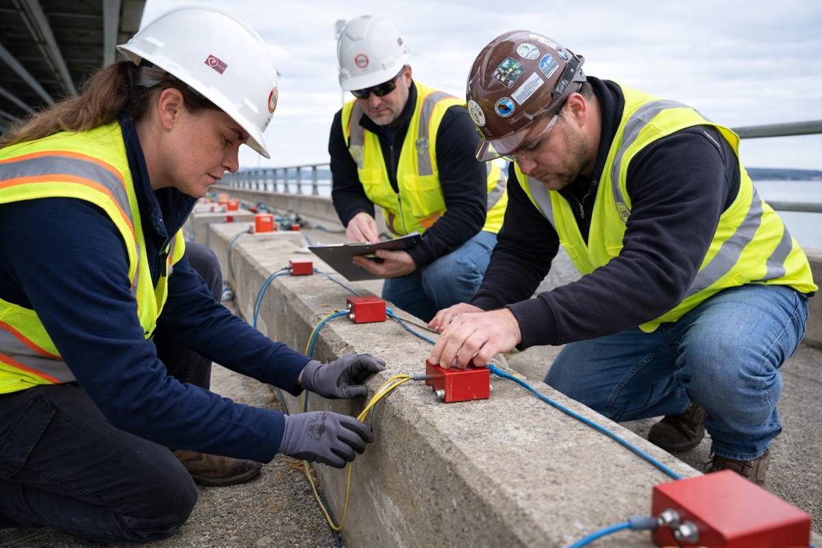
The SHRP2 program (Strategic Highway Research Program 2) demonstrated that combining GPR with complementary methods – infrared thermography and impact-echo – significantly improves condition assessment accuracy. Each method has blind spots. GPR excels at locating metallic targets and measuring moisture content. Infrared identifies near-surface delamination through thermal contrast. Impact-echo detects voids and disbonds acoustically. Used together, they give condition assessors a more complete picture than any single method alone.
The FHWA National Bridge Inventory 2025 data now mandates element-level condition data for all National Highway System bridges – a shift that makes continuous subsurface survey data directly relevant to federal reporting requirements. Agencies that build GPR results into their element-level condition records are satisfying that mandate with higher-quality data than visual inspection alone can provide.
Turning Scan Data Into Maintenance Decisions
Scanning is the data-collection phase. What happens next determines whether the investment pays off.
When GPR results feed into asset management platforms, highway agencies can identify deterioration patterns across a network before the worst-affected segments reach critical condition. A bridge deck showing early-stage rebar corrosion over 15% of its area is a candidate for targeted cathodic protection or localized overlay work. The same deck at 60% delamination is a full deck replacement candidate. The cost difference is substantial. The traffic disruption difference is enormous.
Digital integration extends the value further. Scan data increasingly connects to digital twin models and bridge management systems, where it updates condition ratings, drives deterioration projections, and supports multi-year capital planning.
There are real limitations worth naming. Glass fiber reinforced polymer (GFRP) rebar – increasingly used in corrosion-resistant bridge decks – doesn’t reflect GPR signals the way steel does, because it’s non-metallic. Ultra-high-performance concrete (UHPC) changes scan profiles because of its density. As how smart materials are changing what bridges are built from continues to develop, scan interpretation protocols must develop with them. GPR analysts working with new materials need updated reference data and calibration procedures. The underlying physics is the same; the signal signatures are not.
When the Scan Reveals a Problem: The Role of Structural Steel Repair
Bridge and highway structures rely on welded steel throughout: girders, bearings, expansion joints, connection plates, drainage channels, anchor systems. When inspection identifies structural deterioration in a steel component, repair typically involves welding. And welding introduces its own risk if it isn’t followed by proper thermal treatment.
The physics are straightforward. Welding creates residual stresses and a heat-affected zone (HAZ) where the metal’s microstructure has been changed by the thermal cycle. Those residual stresses don’t dissipate on their own under normal service conditions. In a bridge girder carrying hundreds of thousands of trucks per year, unremediated residual stresses at a repaired weld are a primary mechanism for crack initiation and propagation under fatigue loading.
Teams deploying advanced heat treatment services apply controlled induction or resistance heating to bring the repaired zone to a precise temperature range – typically 595 to 760 degrees Celsius for structural carbon steels – where residual stresses relieve without degrading the material’s toughness or tensile properties. The cycle is controlled, logged, and documented against the applicable code requirements.
ASME B31.3 mandates post-weld heat treatment (PWHT) for carbon steel welds above 19mm wall thickness. For high-alloy steels, it’s required regardless of wall thickness. In corrosive service environments – and bridge steel exposed to chloride-laden de-icing salts qualifies – stress corrosion cracking is a documented consequence of skipping PWHT even where codes don’t strictly require it. A technical review by Hotfoil-EHS confirms that pre-weld heating and PWHT are essential protective measures for infrastructure components in chloride-rich environments where stress corrosion is a live risk.
Modern field PWHT equipment handles complex geometries. Induction coils wrap around connection plates, gussets, and curved sections. Temperature data streams to QC dashboards in real time, giving engineers documented evidence that the heating cycle hit the required range and held it for the required duration. This isn’t bureaucratic box-checking. It’s documented risk reduction on assets that will carry live traffic loads for decades.
And corrosion is quietly accelerating the deterioration of aging steel assets across the bridge inventory. Every year a stressed weld or corroded connection goes untreated is a year of additional fatigue damage accumulating toward a repair that will cost significantly more than the treatment that was skipped.
The Inspection-to-Repair Lifecycle: Connecting Scanning and Treatment
The individual methods are both well established. The less obvious challenge is connecting them into a coherent maintenance workflow rather than treating them as separate work orders triggered by separate events.
Here’s what a complete bridge maintenance intervention looks like in practice. A GPR survey identifies a rebar corrosion zone and subsurface delamination in a specific section of the bridge deck. The same inspection campaign flags a cracked weld on a steel girder during close-up visual assessment. A condition assessment report translates both findings into a prioritized repair sequence with specifications for each defect type.
Concrete rehabilitation addresses the deck: hydrodemolition removes deteriorated concrete to the delamination depth, new concrete is placed and cured. On the steel side, the girder weld repair proceeds with pre-heat applied per code, the weld deposited by a certified welder, and a PWHT cycle conducted and logged against ASME requirements. A post-repair scan confirms no new anomalies were introduced during construction. The structure is documented and returned to service.
This workflow runs on thousands of US bridges every year. But it only delivers full value when scan data and treatment are systematically connected – when the GPR results are in the hands of the repair team before scope is set, and when PWHT is a standard budget line item rather than a negotiable add-on that gets cut under schedule pressure.
According to the ASCE 2025 Infrastructure Report Card for bridges, 221,791 bridge spans need repair or replacement, with identified rehabilitation needs totaling $191.3 billion against a $373 billion funding gap over the next decade. The IIJA directed $40 billion specifically to bridge projects and has funded 12,306 projects since enactment. That’s a substantial investment. It won’t close a $373 billion gap unless it’s spent on the right work in the right sequence – and that requires accurate condition data from subsurface scanning, not just surface observation.
The Case for Getting Both Right
The methods exist. GPR scanning at network scale is proven and operationally practical on live highways. PWHT protocols are code-backed and field-tested with real-time documentation. The gap isn’t technology. It’s systematic integration into standard maintenance programs before bridges reach the poor-condition threshold.
Budget pressure and project timelines push toward shortcuts. Skipping subsurface scanning means repair scope is based on surface observation and guesswork – which produces change orders when contractors hit delamination they didn’t budget for. Skipping post-weld heat treatment saves a few hours upfront but can initiate stress corrosion failures that cost multiples more to remediate after cracking propagates under fatigue loading.
The 2025 ASCE C grade for bridges reflects slow but real improvement, partly from IIJA funding now working through the system. Accelerating that improvement requires embedding inspection and treatment into maintenance cycles before bridges reach critical condition – not as a reaction to visible failure after the damage is already extensive.
Infrastructure agencies that treat GPR scanning and structural heat treatment as standard budget line items – rather than discretionary spending triggered by visible distress – are making a bet on prevention that the nation’s bridge condition data increasingly supports. The alternative is managing a backlog that, by every available metric, is still growing.