






Enerpac Hydraulics Launch Alaska’s 283-Metre Juneau Creek Bridge
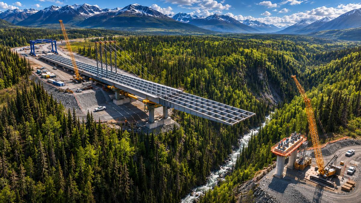
Approximately 3,175 tonnes of structural steel were pushed across Alaska’s Juneau Creek Canyon in June 2026, as construction crews advanced a complete five-girder bridge over one of the most difficult crossings on the Kenai Peninsula. The operation took eight days, with the structure moving across a steep canyon approximately 87 metres above the creek below.
The 283-metre Juneau Creek Bridge was assembled on one side of the canyon before being launched as a single superstructure. A custom hydraulic system supplied by Enerpac provided the pushing, gripping and positioning functions, working alongside temporary steelwork, rollers and structural monitoring equipment designed to control the bridge as its weight transferred between supports.
The crossing forms the centrepiece of Alaska’s Cooper Landing Bypass, part of the Sterling Highway MP 45–60 improvement programme. Although the principal steel structure has reached its final position, construction of the bridge deck and adjoining highway sections continues before the new route can open to traffic.
Briefing
- The 283-metre Juneau Creek Bridge was launched across the canyon as a complete five-girder steel superstructure in June 2026.
- COWI reports approximately 3,175 tonnes of structural steel, with additional temporary launching equipment forming part of the moving assembly.
- Four Enerpac hydraulic cylinders, each rated at 100 tonnes with a three-metre stroke, advanced the bridge in successive controlled movements.
- Structural monitoring, a 55-metre launching nose and temporary cable stays helped manage changing loads, deflection and wind effects.
- The crossing will become Alaska’s highest highway bridge, with the wider Cooper Landing Bypass expected to open in 2030 under the current programme.
Building Across Juneau Creek Canyon
The geography of Juneau Creek Canyon left the construction team with few straightforward options. Steep slopes, limited access beneath the proposed crossing and sensitive surrounding terrain made conventional steel erection difficult, while Alaska’s short construction season complicated any approach that required temporary structures to remain exposed through winter.
The QAP-Traylor joint venture, working with the Alaska Department of Transportation and Public Facilities (DOT&PF), examined several bridge configurations before selecting a three-span steel plate girder design. A tied-arch arrangement was among the alternatives considered, but its likely cantilever erection method would have exposed partially completed steelwork to the canyon’s demanding wind conditions over an extended construction period.
The selected design allowed the entire steel superstructure to be assembled on prepared ground to the east of the canyon, where cranes and conventional erection equipment could operate without having to reach down into the gorge. The bridge comprises five longitudinal girders connected by cross frames and bracing, with a central span of approximately 134 metres and two side spans of around 73 metres.
Unlike conventional incremental launching, where shorter sections are added progressively behind an abutment, the Juneau Creek bridge was assembled to its full length and width before the crossing began. This allowed the main launching operation to be scheduled within a summer weather window, avoiding the prolonged exposure that would have accompanied construction over several seasons.
The logistical work began well before the hydraulic equipment was installed. Steel girder sections weighing up to approximately 68 tonnes were fabricated in Arizona, shipped through Long Beach to Seward in Alaska, and transported by road to the construction site in assembly order. Specialist cranes lifted the sections into position on the launching bed, where crews connected the girders and installed the transverse and lateral bracing.
According to Traylor’s account of the project, the chosen method also reduced the need for construction activity within the environmentally sensitive canyon. Much of the steel assembly could take place on relatively level ground, leaving the most demanding operation concentrated into a comparatively short period.
Hydraulic Launching and Precision Control
Moving the complete superstructure required a hydraulic system capable of advancing the bridge while maintaining control of its position and the forces acting on the launching equipment.
Specialist contractor KWH Constructors provided the launching equipment, site engineering and field personnel, working with Somerset Engineering on the mechanical launching arrangement. Enerpac developed a custom, integrated hydraulic power unit that combined launching, clamping, levelling and guidance functions with a central monitoring system.
Four principal hydraulic cylinders, each rated at 100 tonnes and equipped with a three-metre stroke, generated the forward movement. Operating at a maximum pressure of 160 bar, the cylinders were arranged in two pairs acting on selected girder lines. Enerpac specified a standard operating speed of 12 metres per hour for the launching mechanism, with a faster mode capable of reaching 18 metres per hour during successive operating cycles.
The movement relied on a repeated grip-push-grip sequence. Hydraulic clamping assemblies first secured the girders while the launching cylinders extended, advancing the bridge by approximately three metres. A second set of clamps then held the structure in position while the first set released, allowing the cylinders to retract and prepare for the next stroke. The alternating arrangement maintained control of the steelwork throughout both the pushing and resetting phases.
Four hydraulic clamping cylinders, described by Enerpac as 250-tonne units, operated at pressures up to 700 bar. The pushing and clamping circuits therefore performed different mechanical functions, with the launching cylinders overcoming the resistance of moving the bridge along its engineered supports rather than lifting the entire steel structure vertically.
The custom hydraulic power unit brought these functions together in a containerised installation, incorporating position sensors and pressure transducers connected to a master controller. Operators could monitor cylinder extension and hydraulic loading on a common display, adjusting the movement manually or using automated sequences as conditions allowed.
Enerpac engineers from North America and Madrid supported the project during planning, commissioning and launching. The initial pushing cycles provided an opportunity to compare actual forces and structural behaviour with the expected operating conditions, allowing the team to refine the equipment settings before the bridge advanced further across the canyon.
The mechanical system was designed to move the bridge, but maintaining the structure’s geometry required a separate level of engineering control. As the five girders travelled over successive supports, the forces carried by individual rollers and temporary supports changed, sometimes substantially, even when the overall movement remained slow and carefully synchronised.
Managing Structural Loads and Wind
Erection engineer COWI developed the temporary structural arrangements and staged analysis needed to move the complete bridge safely across the canyon. Its engineering covered the permanent girders, cross frames, bracing, launching nose, temporary king posts, stay cables, rollers and lateral guidance equipment.
Launching five connected girders created a particularly demanding structural problem. Differences in girder camber, support elevation, fabrication tolerances and roller friction could redistribute considerable loads between the individual girder lines. The superstructure could not be treated as a perfectly rigid assembly, and the temporary works had to accommodate predictable movement without creating excessive restraint or unintended forces.
COWI developed detailed three-dimensional models of the bridge throughout the launching sequence, examining changes in support reactions, stresses and deflections as the girders advanced. The analysis also informed modifications to the permanent steelwork, including adjustments to member sizes, splice capacities and bracing where the temporary erection conditions imposed demands beyond those encountered in the completed bridge.
The project team supplemented this modelling with real-time reaction monitoring at the supporting piers. Measurements from individual girder lines allowed engineers to compare actual loads with the predicted behaviour and make adjustments when differential loading approached the design limits. Cylinder position and hydraulic pressure data supplied information about the launching mechanism, while the pier instrumentation helped establish how the bridge itself was responding.
“At every stage of the launch, the structural system changed as the girders moved from one support condition to another. We had to understand how five girder lines, the temporary stays, launching nose, rollers and permanent steel would behave together throughout that process while accounting for wind, seismic demands, camber and the tolerances inherent in a structure of this scale.”
The assessment was given by Claus Fredriksen, Head of Department, Roads and Major Crossings at COWI, in the company’s published account of the erection engineering.
Controlling vertical deflection was especially challenging as the leading end of the bridge extended into the canyon. A lightweight, 55-metre steel launching nose projected ahead of the permanent girders, allowing the leading assembly to reach the receiving supports before the heavier bridge structure arrived. Its geometry and stiffness were selected to balance the need for reduced weight against the substantial forces generated during the longest cantilever stages.
Temporary king posts and stay cables provided additional support, reducing vertical deflection and helping maintain the elevation needed for the launching nose to engage the next pier. At maximum cantilever, approximately 134 metres of the bridge extended beyond its previous permanent support. The structural system changed considerably as the nose made contact with the receiving rollers and the load began transferring onto the next support.
Wind introduced another demanding set of conditions. Juneau Creek Canyon can channel strong airflows through the valley, and the partially launched steelwork presented a very different aerodynamic profile from the finished bridge. The project team worked with specialist wind engineering consultancy RWDI to evaluate the temporary structure under site-specific conditions, including the different wind criteria applicable during the summer launching window and when the equipment was secured out of service.
The assessment examined flutter, galloping and vortex-induced oscillation. While the structure was found to be stable against flutter and galloping under the assessed conditions, vortex-induced oscillation emerged as a governing consideration during certain stages, particularly when the bridge reached its maximum cantilever. The resulting load cases informed the temporary works design and the operating limits used during construction.
These wind criteria were accompanied by temporary seismic assessments and provisions for securing the bridge at intermediate positions if work had to stop. The engineering approach allowed the construction team to respond to changing site conditions while keeping the structural system within its intended limits.
The bridge advanced across the canyon over approximately eight days, with alignment maintained within a reported tolerance of around 25 mm. Its overall progress was considerably slower than the hydraulic cylinders’ nominal operating speeds, as the team checked support reactions, surveyed the steelwork and adjusted the temporary equipment between movements.
“The custom Enerpac Bridge Launching Hydraulic Power Unit was the ideal solution for launching the Juneau Creek Bridge,” said Justin Sieg, Launch Director at KWH Constructors, Inc. “By combining all the bridge launching actions in a single, integrated and containerised HPU we were able to accurately monitor and control the bridge launch at every stage.”
Completing the Bridge and Cooper Landing Bypass
Reaching the opposite side of the canyon completed the horizontal movement, but the superstructure still had to be transferred from its temporary launching supports onto the permanent bearings.
Once the bridge was in position, crews jacked the steelwork upwards to remove the launching rollers before lowering the structure onto its bearing pads. According to Engineering News-Record’s account of the operation, the final lowering involved approximately 1,016 mm of vertical movement, carried out in increments of around 254 mm. This operation required further control of the support reactions as the load paths changed from the temporary erection arrangement to those intended for the completed crossing.
With the principal steelwork secured, construction could progress to the remaining permanent components and concrete bridge deck. Deck work is scheduled for 2027, with further bridge activities continuing into 2028 under the published programme. The completed crossing will stand approximately 87 metres above Juneau Creek, making it Alaska’s highest highway bridge, with a 134-metre main span among the state’s most substantial highway crossings.
The bridge forms part of the wider Sterling Highway MP 45–60 programme, which will reroute approximately 24 kilometres of highway around Cooper Landing. The existing route experiences substantial seasonal traffic associated with tourism, fishing and travel between Anchorage and communities on the Kenai Peninsula, creating congestion through the settlement and along sections close to the Kenai River.
The bypass is intended to improve road safety and traffic flow while reducing the risk of vehicle accidents and hazardous material spills affecting sensitive salmon habitats. The wider programme also includes wildlife crossings and improvements to the surrounding road network, with the completed corridor currently anticipated to open in 2030.
Project costs have increased substantially since the early planning stages. Alaska DOT&PF reported an estimated programme cost of $840 million in 2023, while the state’s October 2026 draft transportation programme placed the projected total at approximately $872 million. The bridge construction contract itself was originally reported at around $151 million, distinct from the full cost of the highway improvements.
The hydraulic launching operation removed one of the most complex construction stages from the programme, although substantial work remains before traffic can use the new route. The combination of full-length steel assembly, staged structural engineering and synchronised hydraulic movement allowed the crossing to be erected without the extensive temporary supports that conventional construction would have required in the canyon.
At Juneau Creek, the demands of the temporary structure influenced the permanent steel design, the construction sequence and the mechanical equipment used to move the bridge. By the time the superstructure was lowered onto its permanent bearings, thousands of tonnes of steel had passed through a succession of structural configurations, each requiring its own combination of hydraulic control, temporary support and monitored load transfer.
Key Industry Questions
- How was the Juneau Creek Bridge launched across the canyon? The complete five-girder steel superstructure was assembled on one side of the canyon and pushed into position using synchronised hydraulic cylinders. Alternating clamping assemblies controlled movement while rollers and temporary supports carried the structural loads.
- How much steel was moved during the launch? COWI reports approximately 3,175 tonnes of structural steel. Enerpac’s original announcement cites a higher moving weight of around 3,420 tonnes, although the reporting does not establish a consistent basis for comparing permanent steel with temporary launching equipment.
- What hydraulic equipment did Enerpac supply? The custom system incorporated four 100-tonne launching cylinders with three-metre strokes, hydraulic clamping assemblies, levelling and guidance functions, and an integrated hydraulic power unit with centralised monitoring and control.
- Why was the bridge assembled before launching? The steep canyon and restricted access beneath the crossing made conventional erection difficult. Full assembly on prepared ground reduced the need for temporary construction works within the canyon and allowed the launch to take place during a selected summer weather window.
- What is the purpose of a launching nose? A launching nose is a temporary steel structure extending ahead of the bridge girders. It reaches the next support before the heavier permanent superstructure and helps control deflection and bending forces during launching.
- How were structural loads monitored? Hydraulic position sensors and pressure transducers monitored the launching equipment, while additional instrumentation measured reactions at the supporting piers. Engineers also used survey data and staged structural analysis to assess movement and load distribution.
- Why were wind conditions a major engineering concern? The partially launched bridge experienced long cantilever stages that differed from its permanent structural arrangement. Site-specific aerodynamic analysis identified vortex-induced oscillation as a governing consideration under certain temporary conditions.
- What happened after the bridge reached the opposite side? The superstructure was jacked upwards to remove the launching rollers, then lowered by approximately one metre in controlled increments onto its permanent bearings. Temporary erection equipment could subsequently be removed.
- When will the Juneau Creek Bridge open to traffic? The concrete deck is scheduled for completion in 2027, with additional bridge work continuing into 2028. The full Cooper Landing Bypass is currently expected to open in 2030.
Strategic Takeaways
- Hydraulic forces were only one part of the engineering challenge. Controlling the bridge’s changing support reactions and geometry required structural monitoring alongside the synchronised pushing system.
- Full-length assembly reduced exposure to difficult site conditions. The steel superstructure could be erected on prepared ground before being moved across the canyon during a shorter summer operating window.
- Temporary erection loads influenced permanent steel design. Member sizes, connections and bracing were refined to accommodate the structural demands encountered during launching.
- Wind engineering shaped the construction method. Vortex-induced oscillation, maximum cantilever conditions and the ability to secure the structure between movements informed the temporary works and operating criteria.
- The final bearing transfer was a separate precision operation. Removing the rollers and lowering the bridge onto permanent supports required another controlled change in load paths after the horizontal launch was complete.