






Why Construction Machines Look the Way They Do
In 1885, an American road inspector named J.D. Adams developed an improvement to the horse-drawn grader that remains recognisable on modern machines. Rather than keeping the front wheels rigidly upright, Adams devised a mechanism that allowed them to lean sideways, helping the grader resist the forces generated as its angled blade moved earth across a road.
The problem was familiar to anyone responsible for maintaining an unpaved highway. A grader blade pushes material sideways as well as forward, generating forces that pull the machine away from its intended course. Adams’ leaning wheels helped counter that movement, giving the operator greater control over the cutting edge. As the Historical Construction Equipment Association records, manufacturers continued to debate the advantages of the design for decades before the principle became widely adopted.
Similar engineering decisions have shaped the machines found on construction sites around the world. The excavator’s boom and stick, the wheel loader’s articulated chassis, the bulldozer’s crawler undercarriage and the asphalt paver’s floating screed all emerged from the need to manage particular forces and working demands. Some designs became industry standards, while others remained valuable in specialist applications.
The first feature in Highways.Today’s Machinery Spotlight Month, From Horsepower to Kilowatts, examined the evolution of the power sources that made modern equipment possible. Machinery design tells the parallel story of how engineers learned to apply that power, and why machines performing similar tasks have converged on recognisable mechanical forms.
Briefing
- The familiar shapes of construction machines reflect engineering decisions about leverage, traction, stability and the movement of material.
- Historical developments such as the Scoopmobile, Caterpillar’s Auto Patrol and Barber-Greene’s floating screed helped establish principles still used in modern equipment.
- Published lifting capacities and drawbar-pull curves show why engine output and operating weight alone provide an incomplete picture of machine performance.
- The backhoe loader demonstrates the commercial value of combining functions, although compact excavators and loaders are changing its position in some markets.
- Electrification and autonomous operation offer new opportunities for machine design, but the forces involved in construction work will continue to shape equipment architecture.
Excavator Geometry and Counterweights
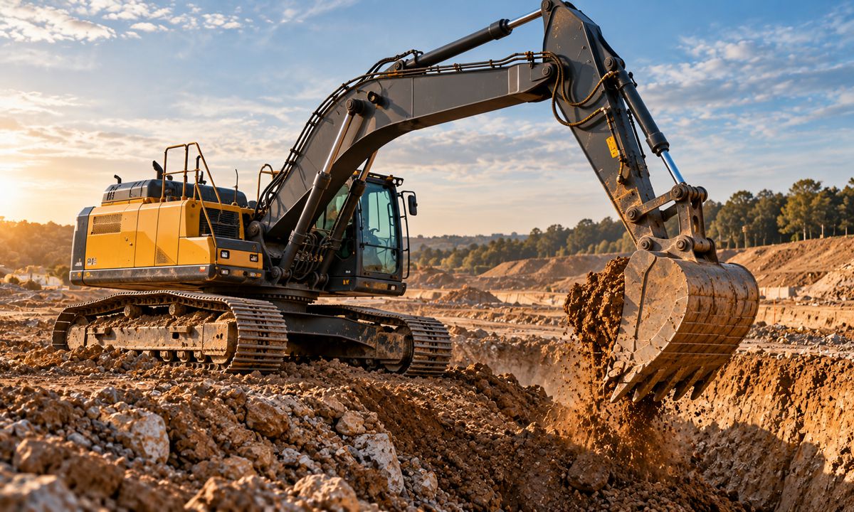
Volvo’s EC220E can lift 7,570 kg along its undercarriage at the manufacturer’s 6.0 m/1.5 m rating point, but only 5,100 kg across it. The engine, hydraulic system and working equipment are unchanged; the difference comes from the direction in which the load acts relative to the tracks.
The figures, published in Volvo Construction Equipment’s comparison of the EC200E and EC220E, expose a fundamental limitation of hydraulic excavators. A machine may have enough hydraulic force to raise a load, but that force cannot be used safely if the chassis cannot resist the overturning moment. Working over the side of the tracks creates a different stability condition from working along their length.
The boom, stick and bucket introduce another layer of complexity. Their pivot positions determine the available digging force as the equipment moves, while extending the stick increases reach and moves the load further from the slew axis. A machine designed for mass excavation therefore has different priorities from one intended for long-reach dredging or confined utility work.
Hydraulic cylinders act through linkages whose mechanical advantage changes continuously during operation. The boom provides the main vertical movement, the stick extends or retracts the working reach, and the bucket rotates to penetrate, collect and discharge material. Their combined movements allow the operator to excavate below track level, reach forward and load a truck without repeatedly repositioning the undercarriage.
The proportions of those components are carefully chosen. A relatively short, robust boom and stick favour high digging forces in demanding material, while long-reach equipment sacrifices some lifting and digging capability to work over a much larger area. Bucket linkages introduce further variation, with breakout force changing as the cutting edge moves through its arc.
Counterweight design is part of the same calculation. Moving mass behind the slew axis improves its contribution to resisting a forward load, but increases the space swept by the rear of the machine. Reduced-tailswing excavators address the clearance problem through tighter packaging, although the forces acting on the machine remain unchanged.
Where an excavator is lifting trench boxes, pipes or heavy attachments, the lifting chart matters more than a headline operating weight. The position of the load, direction of the lift, boom specification and supporting ground determine what the machine can safely handle.
Wheel Loader Articulation and Linkages
The articulated wheel loader emerged from a concrete contractor in Portland, Oregon. Ed Wagner & Sons had developed machinery for handling concrete and needed a better way to load its equipment, prompting the family’s Mixermobile business to experiment with an unusual three-wheeled Scoopmobile.
In 1953, Mixermobile introduced the LD5 and LD10. According to the Historical Construction Equipment Association, these were the first articulated-frame wheel loaders, with nominal bucket capacities of one and two cubic yards respectively.
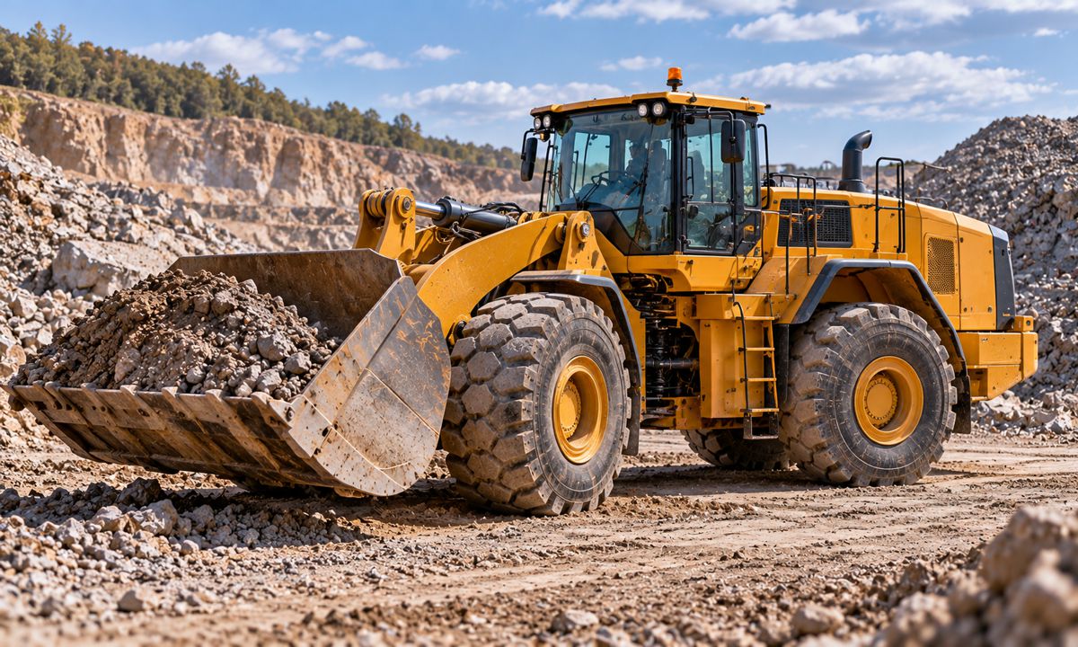
The original sales literature advertised up to 20 degrees of bucket swing. Instead of turning a pair of large front wheels, the machine bent around a joint between its chassis sections, allowing the bucket to point towards the loading face as the operator steered.
The principle offered several advantages. The bucket remained aligned with the front frame during manoeuvring, making repeated approaches to a stockpile easier to control. Large tyres and heavy-duty axles could also be retained without the steering clearance demanded by a conventional rigid chassis.
Mixermobile had demonstrated the advantages of articulation six years before General Motors’ Euclid Division introduced its own articulated loader design in 1959. Yet it was Euclid’s design that established the pattern subsequently adopted across the industry.
Articulation also introduced engineering challenges. The central joint had to transmit loading and travelling forces while allowing the two halves of the machine to steer. As the loader turns, its stability changes, particularly with a raised bucket, making the relationship between the chassis, load and supporting wheels central to its rated capabilities.
The bucket linkage developed alongside the chassis. Z-bar systems use a bellcrank and connecting link to concentrate mechanical advantage where high breakout force is valuable, particularly when penetrating dense stockpiles. Alternative designs place greater emphasis on maintaining attachment orientation during lifting, an advantage when handling pallets, pipes and other loads.
The lift arms determine the bucket’s path as well. Discharge height and forward clearance matter when loading high-sided trucks, while a quarry loader digging into blasted rock places greater emphasis on bucket penetration and efficient loading cycles. Modern wheel loaders are considerably larger and more sophisticated than the early Scoopmobiles, but their chassis and linkages still reflect the same engineering priorities: getting the bucket into material, controlling the load and completing the cycle efficiently.
Crawler Traction and Blade Design
Komatsu’s D155AX-8 develops 268 kW and weighs approximately 41.7 tonnes in the equipment specification published for the European market. Yet its drawbar-pull curve carries a qualification that matters more than either headline figure: the pulling force available from the drivetrain can only be used where the ground provides sufficient traction.
The graph shows how available pulling force changes with travel speed, while the maximum force the machine can sustain remains constrained by its weight and the surface beneath it. A transmission may deliver considerable torque to the final drives, but once the tracks begin to slip or the soil shears beneath them, additional power does little to improve production.
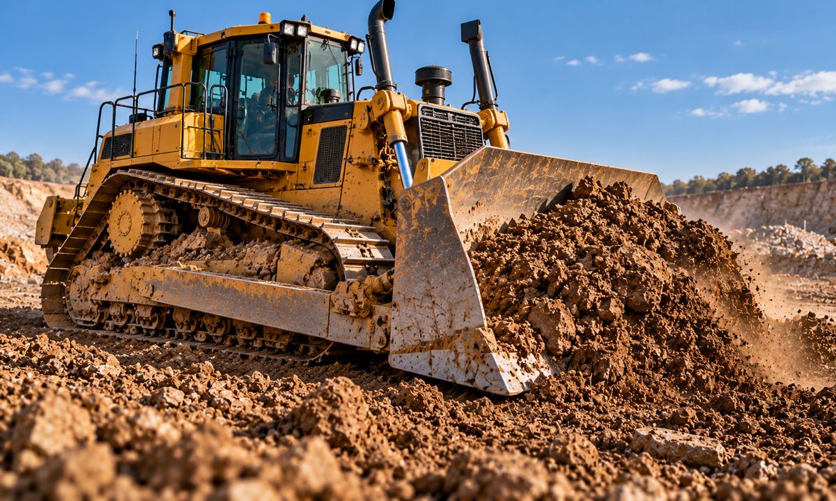
The crawler undercarriage addresses that problem through a long contact area, carefully selected track shoes and grousers that engage the surface. Track width, machine mass and ground strength together determine how effectively the dozer converts available power into movement.
There is no universal benefit in fitting the widest possible tracks. Low-ground-pressure equipment helps a machine travel over weaker surfaces, but spreading its weight over a larger area changes contact pressures and traction characteristics. Heavy earthmoving on firm ground presents different demands from pushing material across saturated soil.
The blade presents another engineering compromise. Straight blades favour controlled cutting and grading, while universal blades use side wings to carry greater volumes of loose material. Semi-universal blades occupy the middle ground, combining carrying capacity with the ability to penetrate more resistant material.
Blade curvature, cutting angle and mounting geometry influence how material enters and moves ahead of the machine. The supporting structure must withstand forces that vary sharply when the cutting edge encounters hard or uneven ground, while the operator needs enough control to manage the load without losing traction.
Modern transmission controls, machine guidance and automated blade positioning have improved productivity, but the essential architecture remains recognisable. The engineering challenge is still to maintain traction and blade control throughout the push.
On difficult ground, a dozer with more installed power may achieve less work than a properly matched machine with the right undercarriage and blade. The ability to transmit force into the ground remains the limiting factor.
Motor Grader Blade Control
The modern motor grader owes much of its layout to a decision Caterpillar made in 1931. Rather than continue fitting grader equipment around an existing tractor, the company developed the Auto Patrol as a purpose-built machine, with the power unit positioned behind the blade.
Caterpillar had acquired Russell Grader Manufacturing on 4 December 1928. Russell’s Motor Patrol, introduced in 1920 and built around an Allis-Chalmers tractor, had already demonstrated the advantages of self-propelled grading equipment. The Auto Patrol took the next step by integrating the power unit, chassis and blade into a dedicated design.
Caterpillar describes the Auto Patrol as the industry’s first true motor grader in its historical account of the machine. Moving the engine to the rear improved the operator’s view of the mouldboard, reduced debris accumulation and improved weight distribution, according to the company’s Auto Patrol archive.
The development also brought increasingly precise blade control. The Historical Construction Equipment Association records that the Auto Patrol’s power-operated controls permitted blade adjustments as fine as approximately 3.2 mm.
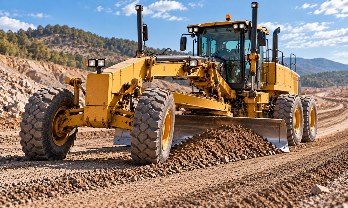
The grader’s long chassis and centrally mounted mouldboard are central to that precision. With the blade positioned between the axles, the machine can shape a surface without transmitting every small movement of its front wheels directly into the cutting edge. The blade circle, drawbar, lateral shift and pitch controls give the operator a wide range of positions for cutting, spreading and finishing material.
J.D. Adams’ leaning-wheel principle, developed in 1885, remained relevant because an angled mouldboard continues to generate lateral forces. Front-wheel lean helps counter those forces, while chassis articulation extends the range of blade positions available to the operator. Tandem rear drive systems provide traction and accommodate the uneven surfaces encountered during grading.
Modern hydraulics and electronic grade control have transformed the operator’s ability to position the blade, but the mechanical relationship between the wheels, chassis and mouldboard remains fundamental. The Auto Patrol established a purpose-built architecture that subsequent manufacturers continued to refine.
The Asphalt Paver and Floating Screed
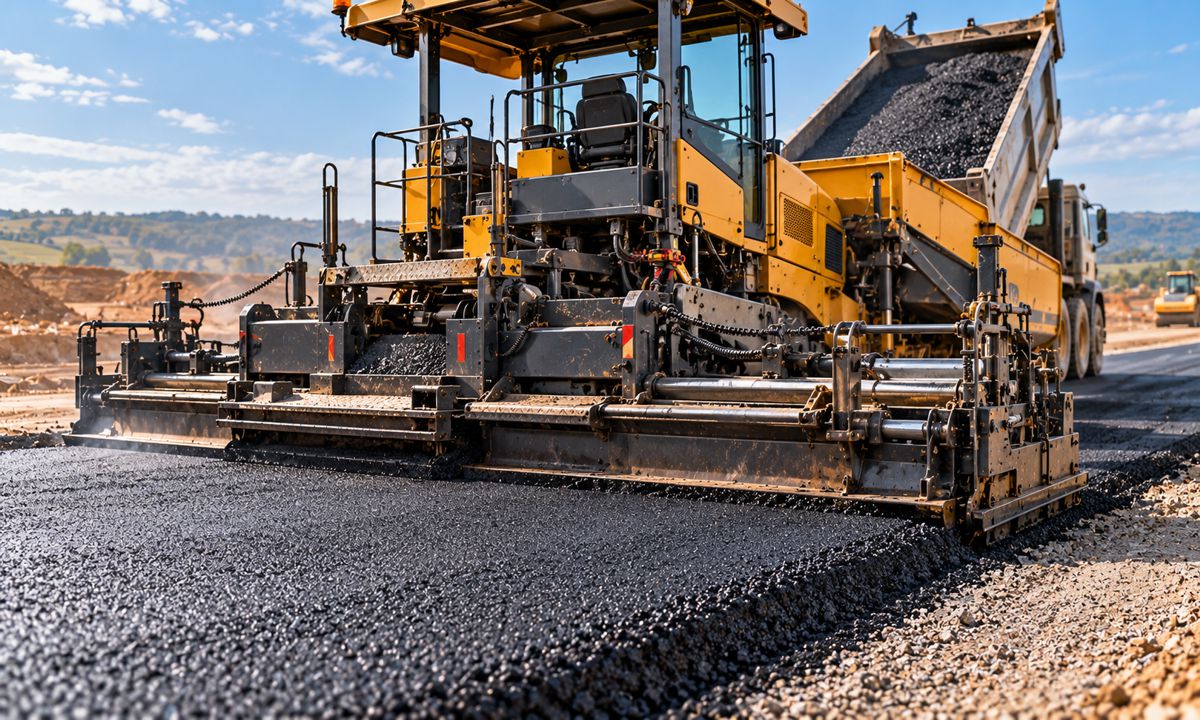
In 1934, Barber-Greene introduced its Model 79 asphalt laydown machine, incorporating a floating screed. The design brought material handling and surface finishing together in a self-propelled machine, establishing a mechanical principle that continues to govern asphalt paving.
As documented by Pavement Interactive, the Model 79 used a sequence that remains recognisable: asphalt entered at the front, moved through the machine, spread across the paving width and passed beneath a trailing screed.
The floating screed was the crucial innovation. Unlike a blade fixed rigidly to the paver’s chassis, it was towed behind the machine through arms connected at tow points. The screed rode on the hot asphalt being placed, with its position determined by the interaction between towing forces, screed weight, material pressure and the resistance of the mixture beneath it.
This allowed the screed to respond differently from the tractor unit as the paver travelled over an uneven base. Rather than reproducing every small chassis movement directly in the finished surface, the screed responded gradually as the forces acting upon it changed.
Pavement Interactive illustrates the behaviour with a rule of thumb. A 25 mm change in tow-point elevation translates to approximately 3 mm at the screed’s leading edge. The screed then takes roughly five tow lengths to settle at a new equilibrium following an adjustment.
Those figures explain why constant corrections can produce an uneven finished surface. Each adjustment initiates a gradual response, and further changes made before the screed has stabilised create variations in mat thickness. An operator attempting to correct every small irregularity may inadvertently introduce the very waves the screed was designed to avoid.
The floating principle is sometimes described as self-levelling, although it does not guarantee a correct surface regardless of operating conditions. Screed angle, tow-point position, paving speed and the amount of asphalt accumulating ahead of the screed all influence its behaviour.
As the Washington Asphalt Pavement Association explains, changes in these forces alter screed elevation and the thickness of the material being placed. Maintaining a consistent head of material is therefore essential to producing a uniform mat.
The paver’s long, low profile follows the movement of material through the machine. The front hopper receives asphalt from delivery vehicles, conveyors carry it towards the rear, and augers distribute it across the paving width before the screed shapes and initially compacts the layer.
The paver and motor grader approach surface accuracy through different mechanical methods. The grader removes and redistributes material with a centrally mounted blade, while the paver relies on a trailing screed supported by the material it places. Both demonstrate how the position and movement of a working element influence the quality of the finished surface.
Hauler Chassis and Ground Conditions
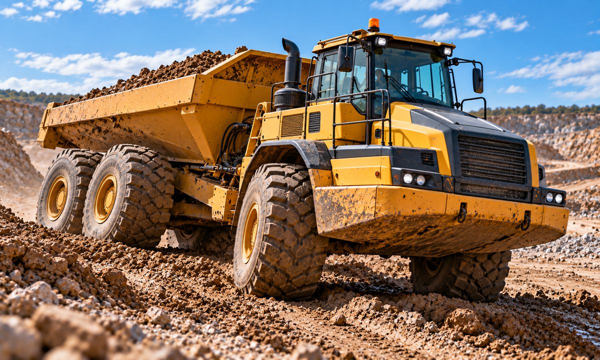
Volvo’s DR631, introduced in 1966 and known as Gravel Charlie, helped establish a different approach to moving material over difficult ground. Developed from tractor and trailer technology, the machine became an early example of the series-produced articulated hauler.
Rigid-frame dump trucks had already established their value in moving large payloads over prepared haul roads. Their structures, tyres, suspension and drivetrains were designed around substantial loads and predictable routes, making them highly productive where road conditions could be maintained.
The articulated hauler addressed a different problem. Its divided chassis allowed the front and rear sections to steer relative to one another, while the oscillation mechanism helped the vehicle negotiate uneven terrain without demanding the same level of road preparation.
Maintaining wheel contact and traction across irregular surfaces became central to the design. The relationship between chassis movement, axle layout, tyres and drivetrain determined how effectively the machine could carry a load over ground that changed as the project progressed.
A rigid mining truck operating on a well-engineered route may move considerably more material per trip, while an articulated hauler offers greater flexibility on developing earthworks sites where surfaces, gradients and access routes change frequently.
The tipping operation introduces another constraint. Raising the body shifts the combined centre of gravity, making ground support and lateral inclination particularly significant. Articulation and oscillation improve mobility, but do not remove the need for stable conditions when discharging material.
These differences influence haul-road investment, operating flexibility and achievable productivity. A larger nominal payload does not automatically produce the lowest cost per tonne when road construction, maintenance and changing site conditions are included in the calculation.
Compaction Drum Design
HAMM conducted its first field trials of oscillation technology in 1983, exploring an alternative to the vertical dynamic forces used in conventional vibratory compaction. The development reflected a broader engineering problem: different materials respond differently to the way a roller applies its weight and movement.
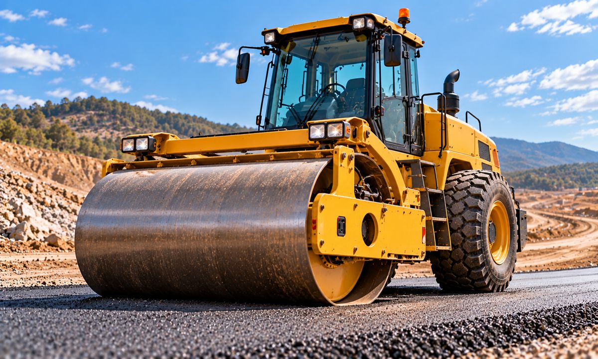
Smooth steel drums, padfoot compactors and pneumatic-tyred rollers each transmit force into the material through a different contact surface. Smooth drums apply load across a relatively continuous area, padfoot drums concentrate pressure through projecting feet, and pneumatic tyres create multiple flexible contact patches.
Vibratory compaction introduced rotating eccentric masses to generate periodic forces within the drum. Frequency and amplitude influence the response of the material, allowing the roller to apply dynamic loading as it travels.
The effectiveness of that movement depends on the material and layer being compacted. Excessive or inappropriate vibration can produce undesirable movement rather than improved density, particularly where the material or underlying structure responds poorly to the selected settings.
Oscillating drums take a different approach. Instead of generating the same predominantly vertical action as a conventional vibratory drum, an oscillation system produces alternating tangential forces, creating a rocking or fore-and-aft movement at the contact surface.
HAMM’s development subsequently became an established part of its roller range, offering an alternative where the response to conventional vibration is a concern. The different motion does not make oscillation universally preferable, but gives contractors another means of matching compaction energy to the material and site.
Modern measurement systems have added a further dimension. Accelerometers and onboard processing identify variations in the roller’s response, while positioning systems associate those measurements with particular locations across the working area.
These measurements help operators assess compaction consistency, but they should not automatically be treated as direct density readings. Material properties, layer thickness and the relationship between the roller and the ground influence the results, making independent verification necessary where specifications require defined density or stiffness values.
The development of compaction machinery has therefore involved more than increasing machine weight. Manufacturers have refined the way force enters the material and the information available to operators, with both influencing the quality and consistency of the finished work.
The Backhoe Loader
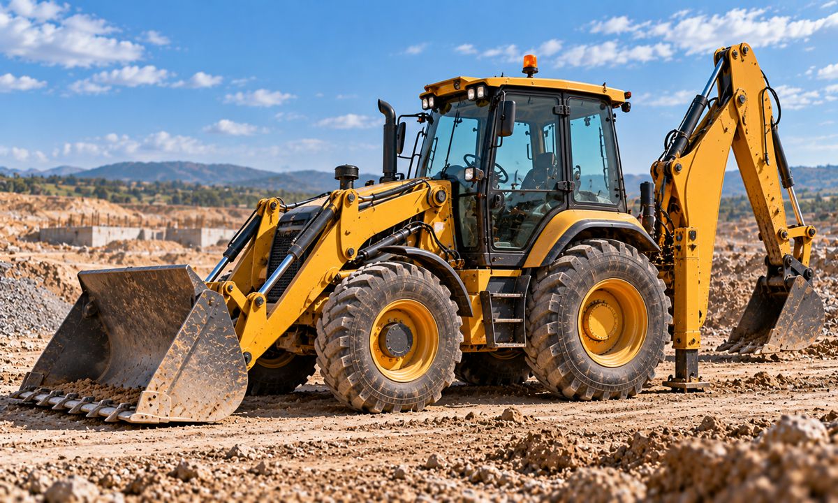
The backhoe loader combines excavation, loading and mobility in a single vehicle, accepting compromises in each function to provide a broader range of capabilities. Its history began with tractor-mounted excavating equipment rather than the fully integrated machines familiar today.
In 1947, Vaino J. Holopainen and Roy E. Handy developed an all-hydraulic digging attachment with a swing-frame mechanism through their work in Hubbardston, Massachusetts. Their Wain-Roy business subsequently supplied hydraulic backhoes for tractor mounting, including a unit sold in April 1948 to Connecticut Light and Power for installation on a Ford 8N tractor.
The swing-frame allowed the digging equipment to move sideways to discharge material without repositioning the carrier. It established a practical feature that would become central to the backhoe’s usefulness, although the original Wain-Roy machine was not identical to the integrated loader-backhoe familiar today.
JCB introduced its Mark One backhoe loader in 1953, bringing a front shovel and rear excavator together on a tractor-based platform. According to the company’s history, only 35 machines were built during 1954, its first full year of production.
In the United States, CASE introduced the Model 320 in February 1957, an important step in the development of the purpose-built integrated loader-backhoe. The machine followed development led by Elton Long and built on CASE’s earlier acquisition of American Tractor Corporation.
Several manufacturers contributed to the concept at different stages, making claims about a single inventor misleading unless the particular design is clearly identified. The progression involved hydraulic backhoe attachments, combined tractor-based machines and eventually dedicated loader-backhoes with chassis, transmissions and hydraulic systems developed around both working functions.
The Mechanics of Two Working Systems
During loading, the machine drives into material, transferring forces through the front bucket, loader arms, chassis and tyres. The structure must withstand the loads generated as the bucket fills and rises while maintaining enough traction and stability to complete the cycle.
Excavation reverses the working direction. The machine becomes a stationary digging platform, with the rear boom and bucket generating forces that act through the chassis and supporting ground. Stabiliser legs extend the support base and transfer loads away from the tyres, while the front bucket contributes to stability when positioned according to the manufacturer’s instructions.
The rear digging equipment uses a boom, dipper and bucket, but normally has a restricted slewing range compared with a conventional excavator. That limitation is one of the compromises involved in combining the two functions on a road-going chassis.
Manufacturers developed different methods of mounting the rear equipment. Centre-pivot designs provide a centrally located digging mechanism, while side-shift systems allow the excavator assembly to move laterally across a rear mounting frame.
JCB’s 1961 JCB 3 was an early example of the side-shift approach, allowing the rear excavator to be positioned for trenching close to walls and other obstructions. The feature became particularly valuable in confined urban sites and narrow road corridors.
The operator’s position reflects the machine’s dual purpose. A rotating seat provides access to the front driving and loading controls as well as the rear excavating controls, while the cab must accommodate visibility and working requirements in both directions.
The result is a demanding mechanical compromise. The front loader cannot be designed independently of the rear excavator, and the chassis must withstand forces that dedicated machines encounter separately.
The Backhoe Loader’s Changing Market
New financed backhoe loader sales in the United States fell 16.7% to 2,120 units during the twelve months ending June 2025, compared with 2,546 in the preceding period. Figures reported by Equipment World, drawing on Fusable’s equipment finance data, also show that backhoes accounted for just 1.4% of new financed machines in the dataset.
Those figures do not establish a worldwide decline, and financed US sales are not a complete measure of the market. They do, however, illustrate the pressure facing a machine whose traditional duties are increasingly shared with compact excavators and compact loaders.
The backhoe loader once offered an especially attractive combination of excavation, loading and road mobility. That remains valuable for utility repairs, municipal maintenance and contractors moving between dispersed jobs. A single machine can excavate a trench, handle material, backfill and travel to the next site without requiring two separate carriers.
On larger projects, or where a compact excavator and loader can remain busy independently, the economics are less favourable. Dedicated machines offer different working envelopes, attachment choices and opportunities for simultaneous operation.
JCB celebrated production of its millionth backhoe loader in January 2025, reflecting the long commercial life of the concept. Its continued success in particular markets does not remove the competitive pressure elsewhere, particularly where contractors have access to a wide range of compact equipment.
The backhoe loader’s strongest commercial position is where mobility, mixed duties and limited machine utilisation make the cost of operating several specialised machines difficult to justify. Its future will be shaped by how much work still rewards that combination.
Multipurpose Machinery and Alternative Designs
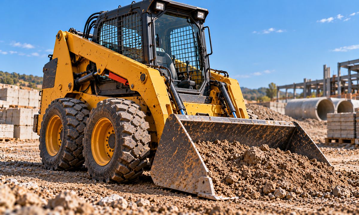
In 1957, brothers Louis and Cyril Keller developed a compact three-wheeled loader for Minnesota turkey farmer Eddie Velo. The machine had to be light enough to reach the upper floor of a turkey barn while remaining sufficiently compact to manoeuvre around the building’s upright posts.
Those restrictions shaped the design. Conventional tractors were too large and heavy for the task, creating a demand for a small machine capable of turning within its own length and operating in confined spaces.
The Keller design attracted the attention of Melroe Manufacturing, which acquired manufacturing rights and employed the brothers to continue development. The subsequent Melroe M-400, introduced in 1960, established the four-wheel-drive skid-steer configuration that would become associated with Bobcat.
The machine solved its manoeuvrability problem through independent control of the wheels on either side. By varying their relative speeds, the loader could turn within a very small area without requiring a conventional steering axle.
That approach remains valuable in confined construction, agricultural and industrial environments, although skid steering has operating costs. Turning can scrub tyres, accelerate wear and damage sensitive or finished surfaces, while compact track loaders introduce different considerations involving track wear, undercarriage maintenance and ground conditions.
Interchangeable attachments subsequently extended the usefulness of compact loaders well beyond material handling. Augers, sweepers, breakers, trenchers and other implements allow the same carrier to undertake numerous operations, provided its hydraulic capacity, stability and structural ratings are suitable.
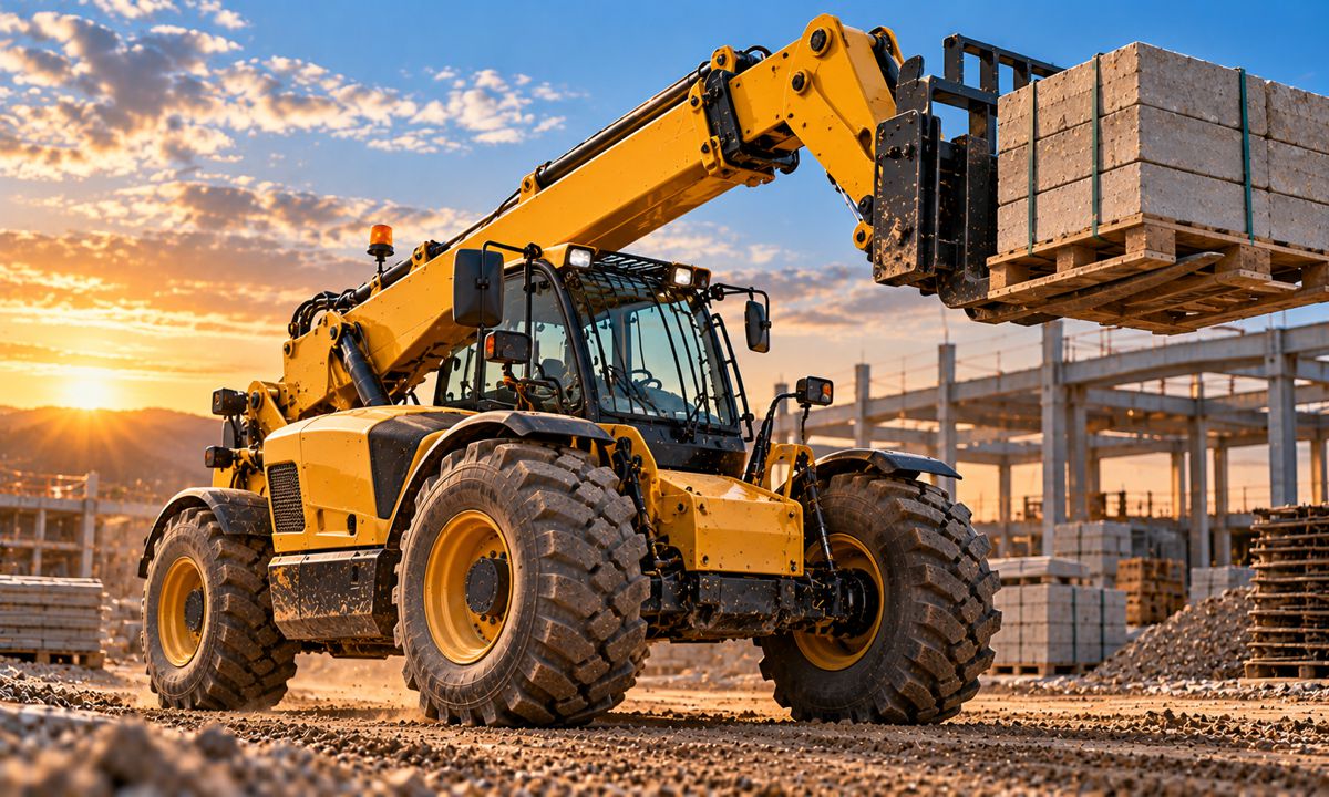
Telehandlers developed around a different requirement, combining the mobility of a wheeled carrier with a telescopic lifting boom. Their defining compromise is the relationship between reach and stability. Extending the boom moves the load further from the machine’s supporting structure, increasing the overturning moment and reducing the permissible load under many operating conditions.
The resulting load charts are a direct expression of the machine’s geometry. A telehandler may be capable of lifting a heavy load close to its chassis while having a much lower permissible capacity at maximum extension.
Other designs have survived in more specialised applications. The Gradall telescopic excavator, developed in the United States during the 1940s, uses a boom that extends and tilts laterally rather than relying solely on the conventional articulated boom and stick.
That design provides working movements suited to particular grading, ditching and road maintenance operations. Cable-operated draglines offer another example, with their long-reach systems remaining valuable in certain mining and bulk excavation applications despite the dominance of hydraulic excavators in general construction.
The continued use of these specialised machines reflects the variety of work undertaken across construction and mining. A design that offers limited advantages in general contracting may remain highly effective where its particular geometry meets a demanding application.
Machine Architecture and Future Design
Electrification and autonomous operation offer opportunities to reconsider established machinery layouts, particularly where engines, transmissions and operator cabs currently impose packaging constraints. Those possibilities were examined in greater detail in From Horsepower to Kilowatts, including distributed electric drive and machines designed without conventional onboard operators.
The underlying forces remain. An excavator must resist overturning moments, a loader must maintain stability as its working equipment rises, and a paver must control the relationship between its material supply and screed. New propulsion and control technologies give designers greater freedom in positioning components, but the value of a different layout will still depend on its ability to perform work reliably and economically.
Machinery Design and Equipment Selection
The evolution of construction machinery has involved continual refinement of the relationship between mechanical force, machine geometry and operating demands. Some designs have remained recognisable for more than a century because their underlying principles continue to deliver reliable performance.
Adams’ leaning wheels helped a grader resist sideways blade forces. Mixermobile pioneered the articulated wheel loader, while Euclid helped establish the design that became the industry standard. Barber-Greene’s floating screed transformed the control of asphalt placement, and the backhoe loader demonstrated the commercial value of combining functions even as the market for those functions began to change.
These developments explain why specifications that appear similar on paper do not necessarily translate into comparable performance. Two excavators with similar operating weights and engine outputs can have markedly different lifting capacities. Two loaders of comparable size may favour different materials and attachments, while a dozer’s pushing performance is governed as much by its undercarriage and the ground beneath it as by the power delivered through its transmission.
Lift charts, tipping-load ratings, attachment compatibility and the geometry of the working equipment therefore belong alongside purchase price, fuel consumption and maintenance requirements in a serious fleet comparison.
Those specifications expose the engineering compromises built into each machine. They also explain why a particular excavator, loader or backhoe may be exceptionally productive on one project and a poor investment on another. Understanding the machinery’s shape is ultimately part of understanding what it will cost to put it to work.
Key Industry Questions
- Why do excavators use a boom, stick and bucket arrangement? The articulated configuration provides a combination of digging force, reach, depth and control. Its geometry allows the bucket to work through a broad operating area, although lifting capacity and digging force change with the position of the equipment.
- What are the compromises of a zero-tailswing excavator? A reduced rear swing radius improves manoeuvrability in confined spaces, but compact packaging changes the positioning of counterweights and other components. Lifting performance, stability, service access and operating clearance must be assessed for the specific machine.
- Why are large wheel loaders usually articulated? Articulation allows large tyres and robust axles to be retained while providing good manoeuvrability. It also keeps the bucket aligned with the front frame during steering, helping operators position the cutting edge when approaching stockpiles.
- Why do bulldozers use crawler tracks? Crawler tracks distribute machine weight and develop traction on difficult ground. Their effectiveness depends on track geometry, machine mass and the strength and condition of the supporting material.
- Why do motor graders lean their front wheels? Wheel lean helps counter the sideways forces generated by an angled mouldboard. The principle dates to J.D. Adams’ 1885 grader design and remains part of modern grader control.
- How does a floating screed improve asphalt paving? The screed is towed behind the paver and supported by the material being placed. Its floating action allows it to respond gradually to changes in towing and supporting forces, helping control mat thickness and surface smoothness.
- What is the difference between vibratory and oscillating rollers? Conventional vibratory rollers generate dynamic loading through rotating eccentric masses, while oscillating drums produce alternating tangential forces and a rocking motion. Their suitability depends on the material, layer and required compaction result.
- When is a backhoe loader preferable to a compact excavator and loader? A backhoe loader is advantageous where jobs are small, varied or spread across several locations. Combining excavation, loading and road mobility reduces transport and equipment requirements, although dedicated machines may be more productive during sustained operations.
- Why do some unusual machinery designs remain in use? Alternative configurations retain advantages in specialist work even when another design dominates the general market. Telescopic excavators, draglines and other specialised machines survive where their working geometry or operating characteristics remain commercially valuable.
Strategic Takeaways
- Useful machine capability is determined by linkage geometry, counterweight position and chassis layout as much as operating weight or installed power.
- Equipment stability and traction depend on the relationship between the machine, its load and the supporting ground.
- Historical innovations such as articulated steering, floating screeds and leaning grader wheels continue to influence modern machinery because they address recurring engineering problems.
- Multipurpose equipment delivers its greatest commercial value where versatility, mobility and utilisation outweigh the productivity advantages of dedicated machines.
- The complete working cycle, transport requirements and site conditions determine the commercial value of a machine alongside its headline specifications.